

If API type is HTTP, this tab is visible.
Enabling Routing/Upstream Settings
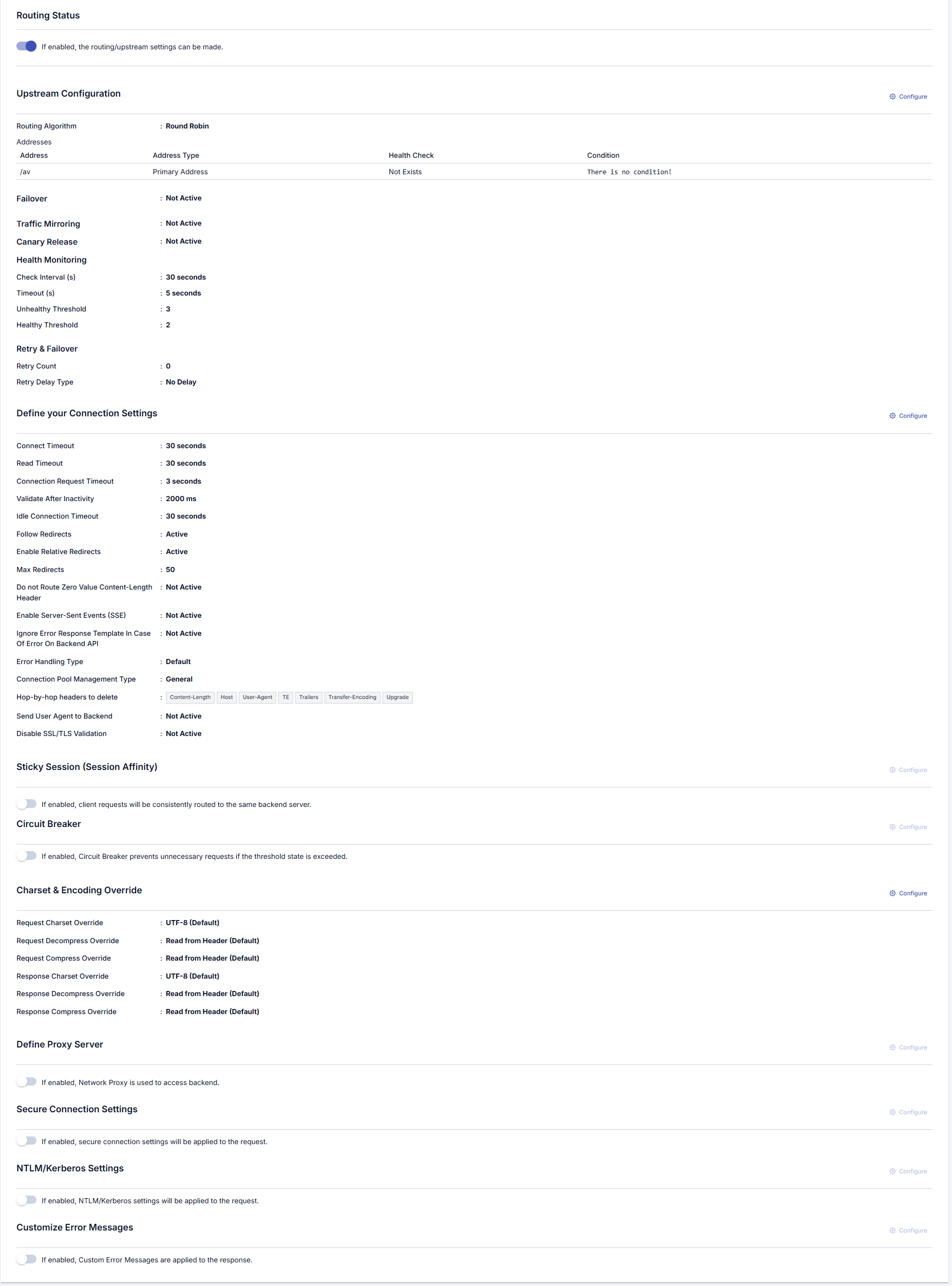
The visual containing the enabling settings for routing/upstream settings is shown below:
Routing Tab settings are shown in the following image:
Managing Backend API Addresses
When creating an API Proxy, the Backend API’s access address can be obtained in different ways:- If an API Definition File is used, at least one of the addresses in this file is selected by the user.
- If an API Proxy is created with the No-Spec API option (for example, for a Backend API developed with code-first approach), the Backend API’s address is entered by the user.
- If an API Proxy is created for an API created with API Creator (DB-2-API, Mock API or Script-2-API), address is not requested, it is managed by Apinizer. The Routing Tab is closed for these types of APIs.

Adding New Address
A new address can be added from the window that opens when the ➕ button in the column header area at the far right of the window opened with the Configure button is clicked.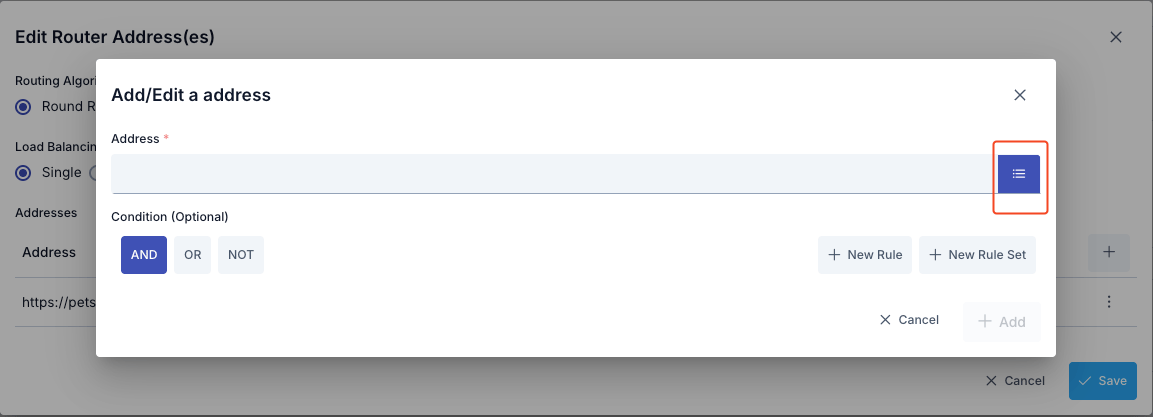
- Backend API address is entered in the Address field or environment variable is used
- Environment Variables Selection Dialog can be opened by clicking the list icon button on the right of the Address field
- Selected environment variable is copied to clipboard and pasted into the Address field
- Conditional routing can be defined with the Condition section
Updating Address
The address can be updated in the window that opens when the Configure button in the Address (Address) column of the table showing addresses is clicked.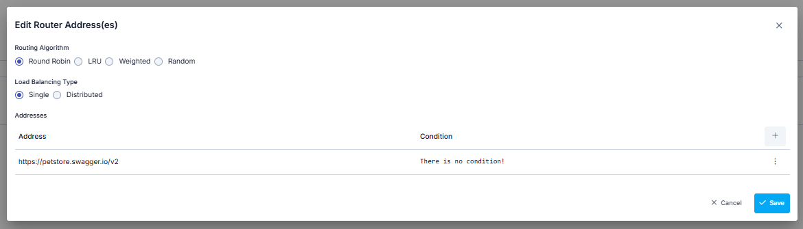
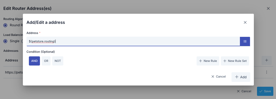
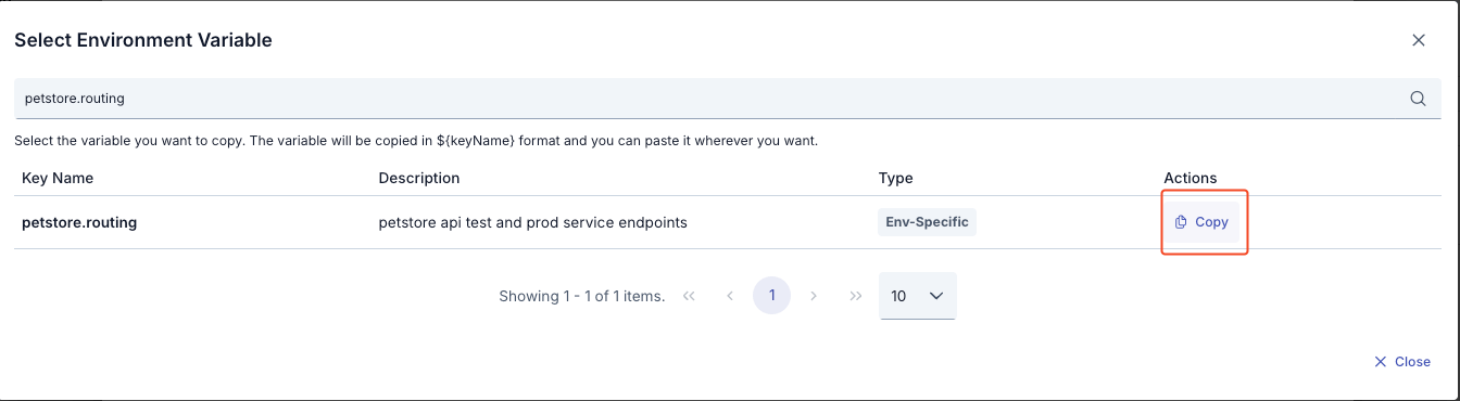
- All environment variables are listed (Global and Environment-Specific)
- Filtering can be done by variable name or description with the search box
- Key Name, Description, Type information is displayed for each variable
- The format of the selected variable (
${variableName}) is automatically copied to clipboard with the Copy button - The copied value can be used by pasting it into the Address field
- Environment variable:
BACKEND_URL = dev-api.example.com(for Development environment) - Environment variable:
BACKEND_URL = api.example.com(for Production environment) - Value entered in Address field:
${BACKEND_URL} - At runtime in Development environment:
dev-api.example.com - At runtime in Production environment:
api.example.com
If the API Proxy’s type is SOAP; the SOAP Type information added/edited in this section is reflected to the port information in the WSDL.
Conditional Routing
The Condition section in the window opened for address update or addition operations provides the ability to define conditions for messages from clients to be sent to this address. Thus, for example, requests that do not come with a special header or parameter value can be routed to only certain one or more of the defined addresses. A practical usage scenario example could be routing requests coming with “test=true” parameter to the test server, and requests that do not contain this parameter to the production server. Another scenario could be routing requests to servers in different regions according to the IP value of the requests.Deleting Address
The address is deleted by selecting the Remove option from the dropdown menu at the end of the row of the address to be deleted.Load Balancing
When the load on the Backend API increases, it is possible to distribute the load by loading the same API/Web Service to another server as well. No network settings need to be made for the new server to be accessible to clients, it is sufficient to add it to the Addresses (Addresses) section on Apinizer. Apinizer distributes the load among these addresses if multiple addresses are defined for a Backend API.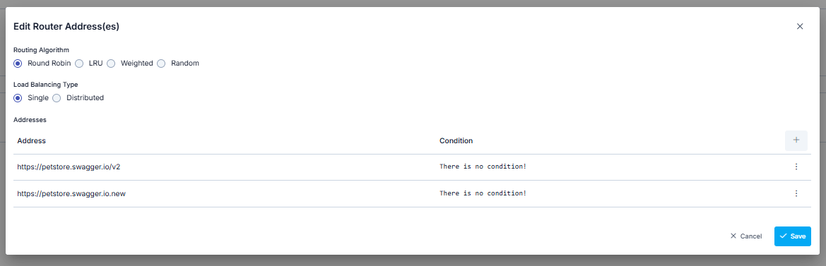
Sticky Session
The Sticky Session mechanism ensures that the same client is always routed to the same backend. This mechanism can be used in scenarios such as session state, cache locality, or backend-specific data consistency. Apinizer supports three different sticky session types: COOKIE_ONLY, IP_HASH, and HYBRID. Cookie-based sticky session uses secure cookies signed with HMAC-SHA256 and works integrated with circuit breaker to automatically skip unhealthy backends.For detailed information, see the Sticky Session page.
Connection Settings Definition
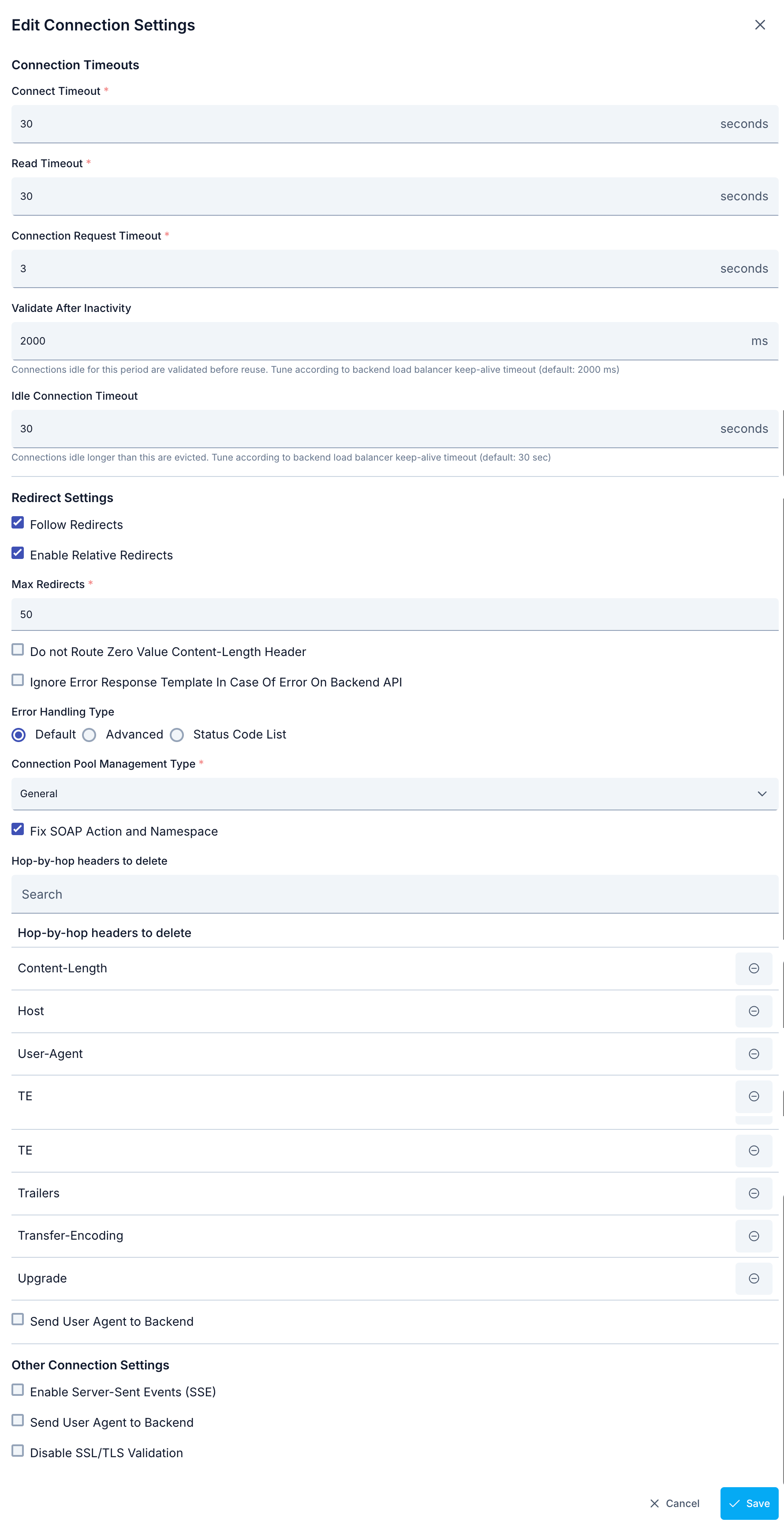
Circuit Breaker
Requests made from clients to APIs can fail due to temporary errors such as slow network connections, timeouts, and overloading or temporary disabling of resources. The causes of such errors can disappear on their own in a short time. However, servers need time for the causes of errors to disappear. Circuit Breaker, a microservice architecture pattern, serves this purpose. Circuit Breaker monitors existing endpoints in a load-balanced system and stops access to the relevant endpoint for a while if there is any abnormality in endpoint responses. At least two addresses must be defined for the Backend API in the addresses section for Circuit Breaker to be usable.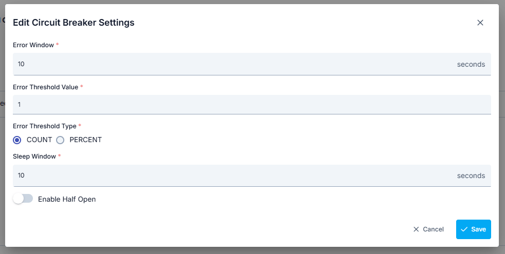
Circuit Breaker is applied separately for each address. When the error threshold and duration are exceeded, the circuit breaker only blocks access to the endpoint at the relevant address.
Automatic Failback with Health Check
The Active Health Check mechanism periodically checks the health status of backends and works integrated with circuit breaker to provide automatic failback. This mechanism automatically removes unhealthy backends from traffic and re-includes them when they become healthy again.How Does Health Check Work?
The health check mechanism works as follows:- Periodic Check: A request is sent to the health check endpoint for each backend at the specified interval (default: 30 seconds)
- Health Status Tracking: The backend’s health status is tracked based on each health check result
- Unhealthy Detection: When consecutive failure count exceeds the fail threshold (default: 3), the backend is marked as unhealthy
- Automatic Disabling: Unhealthy backends are automatically removed from traffic via circuit breaker
- Automatic Recovery: When consecutive success count exceeds the pass threshold (default: 2), the backend is marked as healthy again and included in traffic
Health Check Parameters
Health check parameters are configured at routing level and apply to all backend addresses:If Health Path is empty or null, health check is not performed for that backend and backend health status is not monitored. Health check is only performed for PRIMARY and FAILOVER_ONLY type addresses (if failover is enabled). For CANARY type addresses, health check is performed if canary release is enabled. Health check is not performed for MIRROR type addresses.
Health Check → Circuit Breaker Coordination
The health check mechanism works coordinated with circuit breaker to automatically disable and re-enable backends based on their health status:- Backend Unhealthy: When health check fail threshold is exceeded, circuit breaker automatically transitions to OPEN state and backend is removed from traffic
- Backend Healthy: When health check pass threshold is exceeded, circuit breaker automatically transitions to CLOSED state and backend is re-included in traffic
- Load Balancing Integration: During load balancing, only healthy backends are selected, unhealthy backends are automatically filtered out
Health Check Lifecycle Management
When an API Proxy is deployed, updated, or undeployed, health check records are automatically managed:- Deploy/Update: New backends are added, removed backends are deleted, unchanged backends’ config is updated (health status preserved)
- Undeploy: All backends’ health check records are cleaned up
Retry and Failover
When requests sent to backend APIs fail, automatic retry and failover mechanisms are activated. These mechanisms automatically handle temporary errors and provide high availability.Retry Mechanism
The Retry mechanism ensures that when requests sent to backend fail, they are retried a certain number of times to the same backend address.Retry Parameters
Retry Flow
The retry mechanism is triggered in the following situations:- Timeout: When connection timeout or read timeout occurs
- Error Codes: When HTTP error codes (4xx, 5xx) are returned from the backend
- Connection Errors: When connection errors such as UnknownHostException, MalformedURLException occur
-
Initial request is sent and result is checked:
- If request is successful: Operation is completed
- If request fails: Retry mechanism is activated
-
Retry mechanism:
- If retry count is 0: Failover mechanism is activated
- If retry count is greater than 0: Retry loop is entered
-
Retry loop (from i = 1 to retry count):
- If retry delay is active: Specified duration is waited (exponential backoff or fixed delay)
- Request is retried
- If request is successful: Operation is completed
- If request fails and i < retry count: i is incremented and loop continues
- If request fails and i = retry count: Failover mechanism is activated
Failover Mechanism
The Failover mechanism automatically redirects requests to other backend addresses (addresses of type FAILOVER_ONLY) when one backend address fails.Failover Logic
The failover mechanism works with a simple and clear logic:- Initial Request: Sent to PRIMARY addresses (with load balancing)
- Failure Condition: If the initial request fails and
failoverOnlyEnabled=true - Failover Addresses: Requests are sent sequentially to addresses of type FAILOVER_ONLY
- Failover Retry: Each failover address is tried
failoverRetryCounttimes
Failover Flow
The failover mechanism works as follows:-
Request is sent to PRIMARY backend and retry count attempts are made:
- If request is successful: Operation is completed
- If all attempts fail: Failover check is performed
-
Failover check:
- If
failoverOnlyEnabled = falseornull: Error is returned - If
failoverOnlyEnabled = true: FAILOVER_ONLY type addresses are used
- If
-
FAILOVER_ONLY addresses (tried sequentially):
- First failover address is selected (from health check filtered healthy addresses)
- Failover retry count attempts are made
- If request is successful: Operation is completed
- If request fails: Next failover address is tried
-
Until all failover addresses are tried:
- Each failover address is tried failover retry count times
- First successful address is used and operation is completed
- If all failover addresses fail: Error is returned
Address Types
For detailed information, see the Retry and Failover page.
Server Side Streaming (SSE)
When the Server Side Streaming feature is activated in response settings, it enables responses from APIs that return HTTP responses as Stream, especially like OpenAI, Claude, Gemini, to be transmitted to the client piece by piece rather than in bulk. With this method, the client can receive the response faster and without interruption. When the SSE feature is enabled, connection pool (Connection Pool) and retry (Retry) mechanisms are disabled. Also, partial data sent on the response line is not recorded and cannot be viewed in log traffic. Since SSE creates long-term open connections, connection timeout settings should be configured carefully.Download
If it is desired for the data to be returned as a result of the API Proxy to be downloadable, this feature is activated. Which response message is downloadable is decided by looking at the Content-Type header value in the return value. If the values here are in the list on the Byte Array Content Types page in system settings, it is decided that the returned value is downloadable. If the download option is activated:- If the response content type of the accessed endpoint is downloadable content, it is downloaded as a file.
- If the response content type of the accessed endpoint is not downloadable content, the request is not affected, normal flow continues.
- If the response content type of the accessed endpoint is downloadable content, the content is encoded with Base64 and returned as String.
- If the response content type of the accessed endpoint is not downloadable content, the request is not affected, normal flow continues.
Charset & Encoding Override
The Charset & Encoding Override feature allows explicit control over how request and response bodies are decoded and re-encoded, independent of theContent-Encoding and charset header values. When an override is configured, the header value is ignored and the configured value is applied instead.
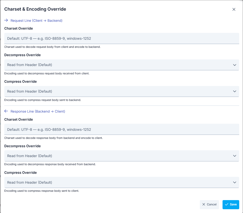
Request Line (Client → Backend)
Response Line (Backend → Client)
Decompress Override options: GZIP, DEFLATE, BR (Brotli), ZSTD, Not Apply (skip).
Request Compress Override options: GZIP, DEFLATE, BR (Brotli), ZSTD, Not Apply (skip).
Response Compress Override options: Mirror server response, Auto by client Accept-Encoding (default), GZIP, DEFLATE, BR (Brotli), ZSTD, Not Apply (skip).
Proxy Server
In some cases, the Backend API address may be behind a proxy server. In such a scenario, the necessary Proxy server settings are made from the Proxy Server section of the Routing tab. The parameters used for Proxy Server configuration are shown below.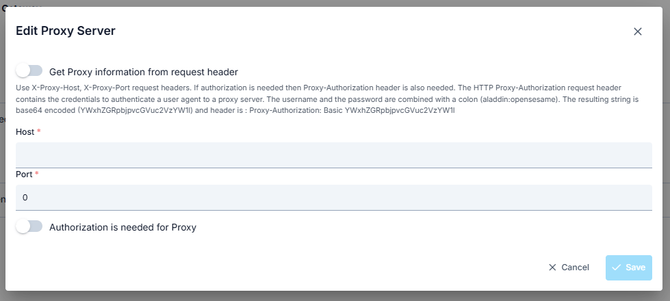
mTLS Setting
When this setting is enabled, the selected mTLS settings are applied to the request. Thus, the Apinizer client that will send from Apinizer to the target service verifies the target service’s certificate and indicates that it also has a certificate and must be verified by the target service. The target service also verifies the client’s certificate, and thus secure communication is established with the client. The parameters used for mTLS configuration are shown below.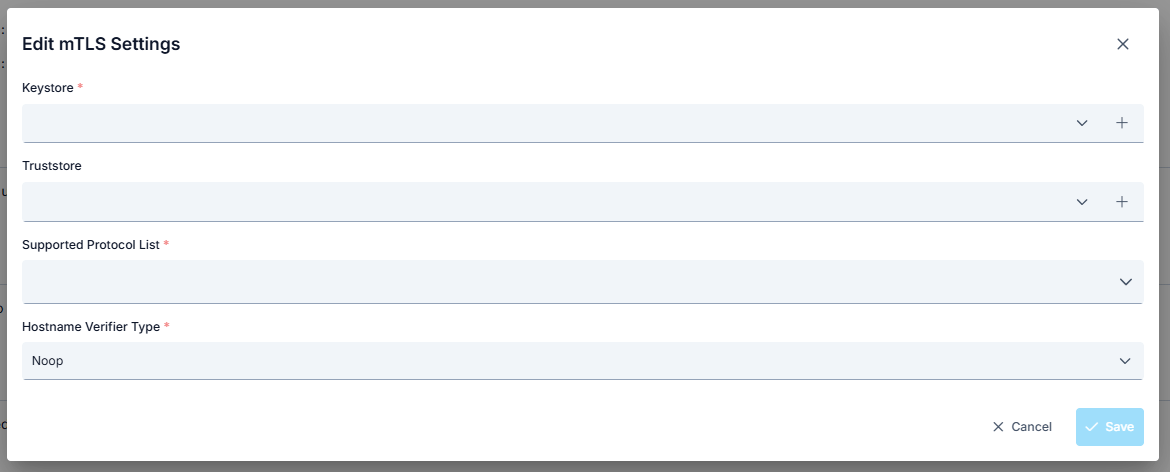
When mTLS settings are active, the existing “http connection pool” in routing, whose values are specified in environment settings, is disabled.
NTLM Setting
When this setting is enabled, the selected NTLM settings are applied to the request. The parameters used for NTLM configuration are shown below.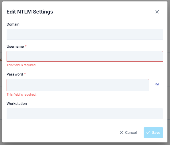
Customize Error Messages
When an error is thrown from policies, Apinizer sends the default error message to the user if it has not been customized. Click to learn more about customizing error messages.See.For a complete guide on all layers, workflow and scenario examples of the error message configuration system, see the Error Message Configuration Guide page.
Important Notes
- If the request
Content-EncodingorTransfer-Encodingheader from the client contains one of “gzip, deflate, br, zstd, compress”, the message body is decompressed using that method, and after request line policies are applied, the body is re-compressed using the same method before being sent to the Backend API. - If the response from the Backend API contains a
Content-Encodingheader, the body is decompressed and, after response line policies are applied, it is processed according to the Response Compress Override setting. The default behavior (Auto by client Accept-Encoding) compresses with the first method the client accepts. - Even when the Backend API returns plain text, the Auto by client Accept-Encoding mode applies the method specified in the client’s
Accept-Encodingheader. The Mirror server response mode forwards the response as plain text. - Policies always operate on uncompressed (plain) data.